"Raspberry Cobbler"
The DIY Raspberry Pi Laptop
Gord Payne - 2018
As part of the TLLP Robotics Project, I was provided with a Raspberry Pi computer.
There are several examples of do-it-yourself RaspPi laptop builds on the web so I decided to give it a shot and build my own.
Parts Required:
Raspberry Pi 3B computer
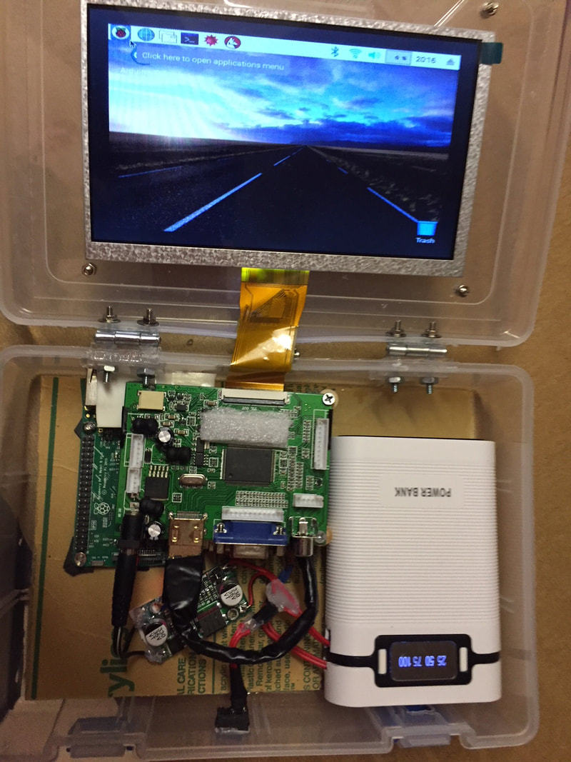
7" Colour LED screen with display driver board
3A 30W DC-DC Boost Buck Adjustable Step Up Down Power Converter
5V/2.5A 10000mAh Battery Case Power Bank Case - 4 cell
4 x Rechargeable Batteries 3.7V 1200/1500/2200/2600 mAh Li-ion Battery
2 x Friction Hinge to hold screen at desired angle for viewing
Bluetooth Mouse and Keyboard
Short length HDMI Male-Male cable
Some kind of enclosure (I used the box the RaspPi kit came in - others have made cases from cardboard, wood, plexiglass
etc.)
The power pack has a nice feature of having a 'power level remaining' display on the outside. This is a nice-to-have, but not required. The power pack turns on/off from buttons on the pack. if you don't have such a pack, you'll need to install a Single-pole-single-throw on-off toggle switch so you can turn your unit on/off.
There are several options for display panels and I thought I'd ordered a product that would directly connect to the GPIO pins on the RaspPi and need no other power supply. Unfortunately, I ordered a unit with a display controller board that required it's own 12V 2.5A power supply. Between this unit and the power requirements of the RaspPi (which needs 5V at 2.5A), The power pack is able to provide adequate power and current, but not much else.
The advantage of this style of display controller is that it leaves all the GPIO pins on the RaspPi available for use in control projects. Also, this board contains HDMI, Composite and VGA output ports giving you lots of options for hooking your laptop up to different displays.
I modified the battery case as follows: I soldered two leads each onto the inside positive and negative sides of the 2A USB outlet. Then I ran the leads out of the case. One pair goes to the In+ and In- pads on the power converter. The other pair goes to a Micro USB male connector that will feed 5V to the RaspPi. To save space, I cut down the Micro USB male cable and connector. I removed the plastic cover to the plug and removed the insulation and shielding from the wires. The leads are just long enough to go from the power pack to the Power-In connector on the RaspPi.
From the power converter, I ran leads from the Out+ and Out- pads to a male power connector that feeds the display board.
There are several examples of do-it-yourself RaspPi laptop builds on the web so I decided to give it a shot and build my own.
Parts Required:
Raspberry Pi 3B computer
7" Colour LED screen with display driver board
3A 30W DC-DC Boost Buck Adjustable Step Up Down Power Converter
5V/2.5A 10000mAh Battery Case Power Bank Case - 4 cell
4 x Rechargeable Batteries 3.7V 1200/1500/2200/2600 mAh Li-ion Battery
2 x Friction Hinge to hold screen at desired angle for viewing
Bluetooth Mouse and Keyboard
Short length HDMI Male-Male cable
Some kind of enclosure (I used the box the RaspPi kit came in - others have made cases from cardboard, wood, plexiglass
etc.)
The power pack has a nice feature of having a 'power level remaining' display on the outside. This is a nice-to-have, but not required. The power pack turns on/off from buttons on the pack. if you don't have such a pack, you'll need to install a Single-pole-single-throw on-off toggle switch so you can turn your unit on/off.
There are several options for display panels and I thought I'd ordered a product that would directly connect to the GPIO pins on the RaspPi and need no other power supply. Unfortunately, I ordered a unit with a display controller board that required it's own 12V 2.5A power supply. Between this unit and the power requirements of the RaspPi (which needs 5V at 2.5A), The power pack is able to provide adequate power and current, but not much else.
The advantage of this style of display controller is that it leaves all the GPIO pins on the RaspPi available for use in control projects. Also, this board contains HDMI, Composite and VGA output ports giving you lots of options for hooking your laptop up to different displays.
I modified the battery case as follows: I soldered two leads each onto the inside positive and negative sides of the 2A USB outlet. Then I ran the leads out of the case. One pair goes to the In+ and In- pads on the power converter. The other pair goes to a Micro USB male connector that will feed 5V to the RaspPi. To save space, I cut down the Micro USB male cable and connector. I removed the plastic cover to the plug and removed the insulation and shielding from the wires. The leads are just long enough to go from the power pack to the Power-In connector on the RaspPi.
From the power converter, I ran leads from the Out+ and Out- pads to a male power connector that feeds the display board.
|
|
|
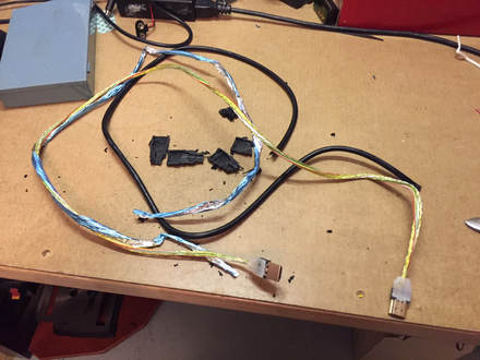
BEFORE - 1 metre long HDMI cable - disassembled
|
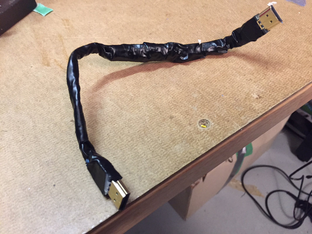
AFTER - 15cm customized cable
|
The HDMI cable to connect the RaspPi to the display driver is far too long to fit in the small case for the whole project. I ordered a smaller ribbon-style cable but it was still too bulky and inflexible to fit the case. I took the risk and removed the insulation and connector covers from the long cable. Then I put tape labels on each shielded pair of wires before cutting the cable down to a 15cm total length. It was then a matter of carefully un-shielding the wires, soldering them together and attempting to re-insulate and re-shield the wires back into a shorter cable. It took over an hour, but I lucked out and it worked!
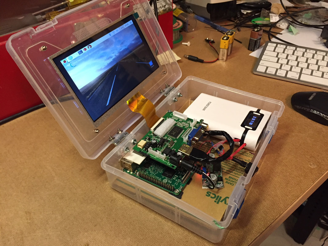
The friction hinges were intended to hold the lid of the box at any desired angle for optimal screen viewing. Unfortunately I broke one of the hinges trying to bend it to fit. I wound up using two small hinges and the single friction hinge in the centre of the lid. It works well.
Finally, I used a soldering iron with a hot-knife attachment to cut access holes in the enclosure for the USB/ethernet ports on the back, the rocker switch in the front (in my project, it just provides power to the display board) and a small hole in the front to allow connection of a Micro USB cable for re-charging the power pack.
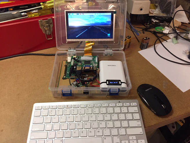
After assembling all the components, I powered it up and paired the USB mouse and keyboard. It works great!
I'm waiting for two very small laptop-screen speakers to arrive that I'll solder onto an audio plug and then plug into the RaspPi.
The battery pack lasts at least and hour and probably substantially longer. I haven't pushed it at this point.
I've had no prior experience with the RaspBerry Pi. This was a challenging project that was a fun exercise in optimizing space, problem solving and bringing together several disparate 'off-use' parts to build a finished product.
This project was cobbled together from various parts and other bits. Ergo it's a 'Raspberry Cobbler!'
|
|
What would I do differently?
Providing enough power to the display and the Raspberry Pi was challenging and I'm not sure about the long term reliability of using the 5V power pack and the up-converter to provide the 12V to the display. I think the current draw of the two boards are probably just minimally supplied by this power pack.
In hindsight, I would preferably use an appropriately sized, 12V lead-acid (or LiPo) battery that has several amp hours of current supply instead. I would supply the display directly with 12V from the battery and then use a 12V-to-5V buck down-converter to provide the 5V to the Raspberry Pi. I believe this would be a better power supply for the components with more than ample current availability. It would be almost the same price and about the same weight.
Live and learn.
